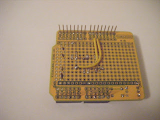
What: A self built motor controller shield that fits on top of your Arduino.
Why: Why should I build my own motor driver shield when I can just buy one that looks nicer too?
There are many benefits that I have found from building your own motor driver shield mainly for beginners. Learning how the motor driver works, and how the different pins on the chip function. You get a better understanding of how it works. The cost of all the parts works out to be cheaper. Improve skills such as; soldering, circuit layout, and troubleshooting these circuits. If you have never dealt with motor drivers before, definitely recommend
Required Tools, Bits & Pieces.
· Soldering Iron & solder
· Wire
· Wire Cutters
· Pliers
Shopping List:
The entire shopping list has been created on Little Bird Electronics with all the 12 different items you will need. Some of these items are interchangeable for others, or are already sitting in your electronics area.
Click Here for your shopping List (LBE Link) (Check Quantity of each item below)
| Item | Quantity |
| Basic Freetronics Proto-Shield | x1 (Comes in Pack of 5 –worth having the spares) |
| H-Bridge Motor Driver 1A | x1 |
| IC Socket – 16 Pin | x1 |
| Arduino Stackable Header – 8 Pin | x2 |
| Arduino Stackable Header – 6 Pin | x2 |
| 2 Way PCB Mount Screw terminals | x1 |
| Mini Push Button Switch | x1 |
| Basic LED – 3mm | x1 |
| Resistor – 330 Ohm | x1 |
| Electrolytic Decoupling Capacitors – 10uF/25V | x1 |
| Voltage Regulator 5V | x1 |
| Heatsink TO-220 | x1 |
| 2 Pin – Female Header | x1 |
Total project cost per shield at time of build. ~$19.00 AUD on 27/10/2010 (Not Including Postage)
*********************************************************************************
Project Build
The following is the process used to make and test your DIY Motor Driver Arduino Shield. Gather all components, required tools, and let’s get started.
Step 1.-Setup
Place Tactile Switch, 330 Ohm Resistor, and the 3mm LED onto the Basic proto-shield.
Once you are happy with the placement. Solder the components in position.
Step 2.-Placement
Next is to start looking at where all the components are going to go on the proto shield. Once you have drawn out where all your components are going to go, remove them keeping note of where they were placed.
[*Although you can see my version, try designing your own layout for practice. Use a drawing program, on the computer, or just a marker on the proto-shield itself*]
Place the IC Socket onto the board and solder just enough pins to hold it in place (Makes it easier in later steps)
Next is to Solder socket pins 1, 9, & 16 to +5V rail. (Now is a good time to mark where Pin1 is on the socket.) This allows Motor Driver power (Pin 16) and permanently enables motors through (Pin 1 & Pin 9)
[*IC Numbering generally starts in the corner and then numbers counter clockwise*]
You should now have something similar to this...
Step 3.-Arduino PWM Pins
Solder Pins of the socket 4,5,12 & 13 to the Ground Rail. As these are the grounding pins for our Motor Driver.
Next is to solder the Arduino PWM pins to the IC Socket. This is done to control the motor speed and direction through the Arduino. I have selected Pins 5, 6, 9 & 10. If you change these, remember to change the testing code later on.
-Solder Arduino Digital Pin 6 to Socket IC Pin number 15
-Solder Arduino Digital Pin 5 to Socket IC Pin number 10
Our current progress looks like....
Turn the Proto-Sheild Over
Solder Arduino Digital Pin 9 to Socket IC Pin number 2
Solder Arduino Digital Pin 10 to Socket IC Pin number 7
The bottom should now look similar to
(My Soldering skills aren’t the best because of my tremors. Please don’t judge me :P)
Step 4.-Arduino Headers
Solder in the Arduino Header Pins (All 4)
Depending on what you available, you could be use blu-tack to hold the headers in place. However I highly recommend Using John’s method from tronixstuff Here
Step 5.- Terminal Blocks
Wiring the terminal blocks into the shield and IC Socket comes next. This was the trickiest one for me to solder. You need to solder IC Socket Pins 3&6 to one terminal block, and IC Socket Pins 11 & 14 to the other terminal block. So it ends up looking like the below.
I soldered the pre-cut wires to the IC Socket Pins. Then pushed the terminal blocks through and soldered the remaining ends. But whatever works for you : )
Step 6.- Voltage for the Motors
We now have our final step before we can test our device.
Remembering the placement you initially had, position the regulator on the proto-shield and solder. Screw the heatsink onto the back the voltage regulator, If you want you can bend the regulator so it lays down as shown in Step 7. The heatsink is not required, however as we are driving motors and pulling alot of current, the regulator may get hot. Best to play it safe ;)
When putting the Voltage regulator in, always make sure you wire it up correctly from the data sheet. If using the suggested LBE 5V Regulator the following picture simply explains wiring. The Red “+” is the Supply Voltage from an external source. The Dashes (in the middle) is the electronic symbol for ground. And the green “5” is the 5V Regulated power supply.
Step 7.
There we have our self built DIY Motor Driver Arduino Sheild.
Step 8. - Testing & Troubleshooting
Testing Code to be written in simple commented format
Will be updated by 5th November 2010.


No comments:
Post a Comment